evoVIU Dokumentation
-
Einleitung
-
Allgemeines & Sicherheit
-
Hardware
-
Software
-
- Articles coming soon
In this chapter, you will learn how the workflow is structured. The individual components are presented for this purpose.
With the workflows, it should be possible to define the process flow and Machine Vision on the evoVIU graphically and without textual programming. Commands and expressions are represented by nodes, the execution sequence and data dependencies by edges. To understand the concept of the workflow, you first need to get an overview of the various components.
The workflow can be roughly divided into 2 large areas:
-
The overview page of all workflows
-
The logic part
1. the overview page
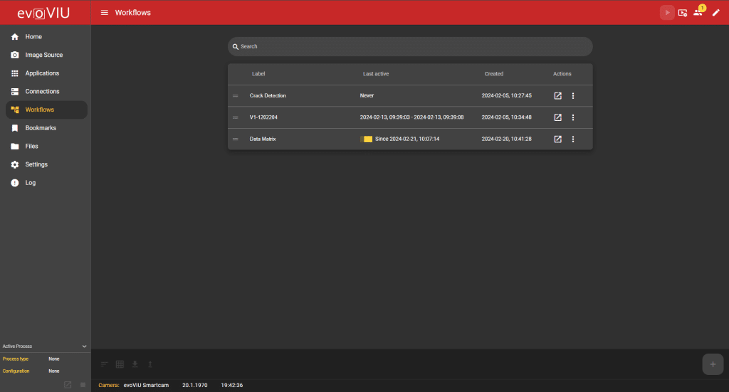
On the overview page, you can see the list of all current workflows on the camera. This list contains information such as the creation date and the time of the last active workflow. You can also delete, move, export, duplicate or edit selected workflows via a three-point menu. You can create a new workflow using the plus button in the bottom right-hand corner. To create a new workflow, a name must be entered in the dialog box.
2. workflow logic
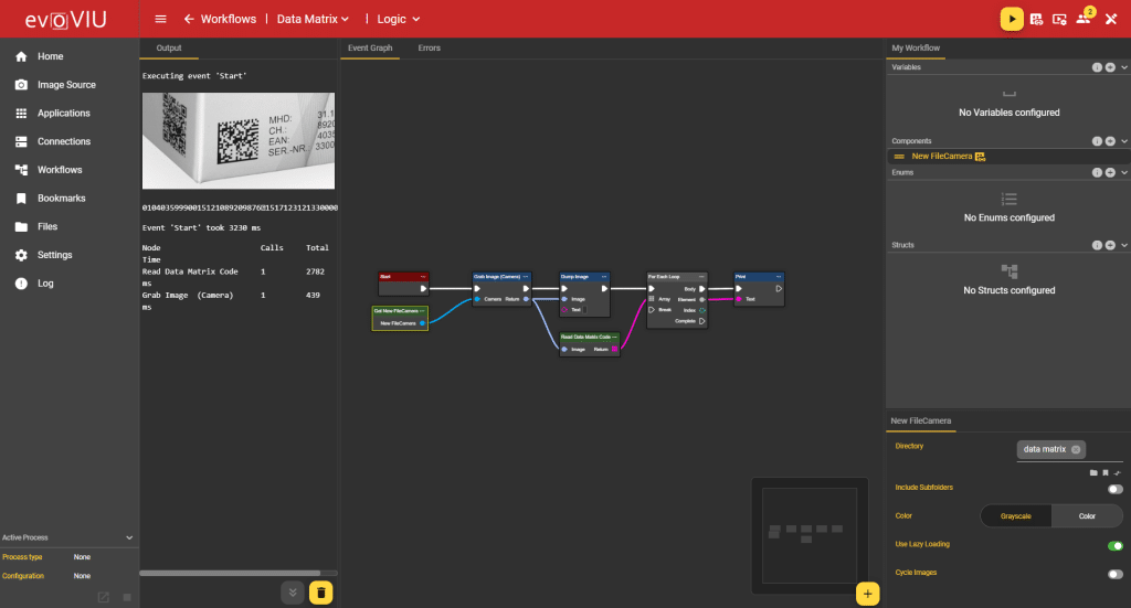
In the Logic area of the workflow, you configure the workflow, which consists of nodes (node elements) and connection elements. The workflow is processed sequentially and presents the desired results in the output window. In addition, certain nodes make it possible to define actions for processing the results after they have been evaluated.
The workflow can be started and stopped using the plus icon in the header.
Before starting to create a workflow, it is important to understand the different windows in Workflow Logic.
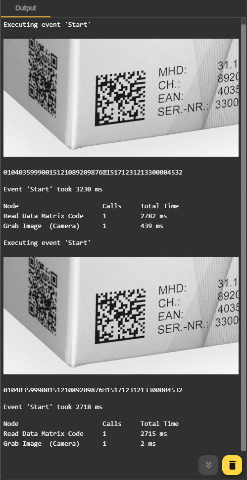
Output window
This window shows the results of the workflow. When a workflow is started, the output window tracks exactly what is happening in the background. At the beginning, the trigger of the workflow is usually displayed, i.e. which event starts the workflow. The activated nodes are then listed. If these nodes deliver results, these are also visible in the output window. In the event of workflow errors, these are also displayed for the user in the output window.
Previous information can be removed by pressing the delete button in the output window. This can help to maintain a better overview, especially when a lot of information is displayed. A click on the button to the left always leads to the latest results.
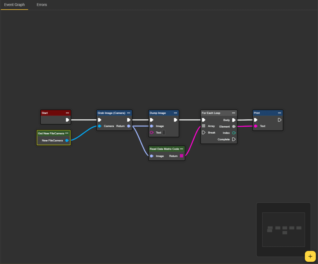
Event Graph
This is the area for the visual representation of your workflow. This is where you place the required nodes and connect them to each other. To create a node, you can either right-click in the Event Graph section or use the plus icon in the bottom right-hand corner. This opens a dialog with all available nodes. Use the search function or navigate through the various categories to find the right node. You can find the documentation for all nodes here. After selecting the node, the dialog disappears and the node appears in the event graph window. If you want to remove a node, click on the three-dot menu in the node and select the “Remove” option.
To connect nodes to each other, click on the connecting elements of the nodes, drag them with the mouse to the next node and click on the connecting element again. This creates a line between the two nodes.
It is important to note that not every node can be connected to every other node. The data types must always match. This can be recognized by the colors and symbols of the connecting elements. For example, you cannot connect an image output to a string input element, as this is immediately prevented. The icons and colors assigned to each file type can be identified by hovering over the icons.
A mini-map is also available in the Event Graph. This is used for orientation and shows where your nodes are distributed in the graph.
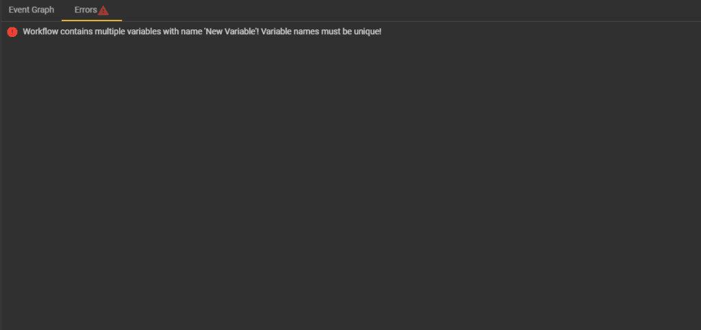
Errors
The Errors tab should ideally be empty. However, if errors occur in the workflow, they will be listed here. Each error is displayed with the corresponding location in the editor and instructions on how to rectify it. Errors may occur in the schemas under “My Workflow” and need to be corrected there. You can see that there are errors if there is a red exclamation mark icon next to the Errors tab.
My Workflow
There are four categories of user-defined nodes in the “My Workflow” section: Variables, Components, Enums and Structs. These can be created individually and integrated into the workflow via get and set nodes. You can edit these user-defined nodes by clicking on them. This causes the corresponding node to appear in the bottom right-hand corner of the window and, depending on the type, offers various setting options.
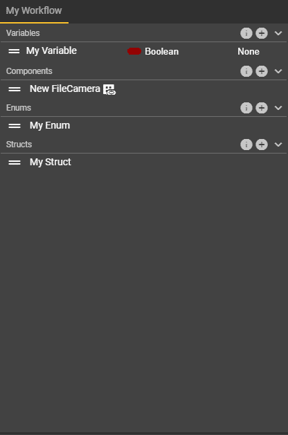
To create a new custom node, click on the plus icon of the desired custom node. For variables, enums and structs, your new node appears directly in the list, while for components you can select which component you want to add from a drop-down menu. You can give the nodes individual names by clicking on the current label. The entries can be deleted again by clicking on the trash can icon. For variables, select the type by clicking on the current type and selecting your desired type from the drop-down list. As soon as a user-defined node has been added to the list, it can be added to the event graph.
Variables
You can save any relevant data type that is required for your workflow as a variable. This includes primitive data types such as strings, enums, booleans or integers, as well as created enums or structs. Select the corresponding data type in your list and specify whether it is an array or not. You can activate or deactivate the “Publish Value” field in the corresponding Details window at the bottom right. If you activate this, the values of the “Values” are displayed and passed on.
Components
As the name suggests, user-specific (hardware) components can be added to nodes here. These include:
Camera
This component allows you to access an image source that you have created.
As soon as an image source is selected, all settings that have already been made in the image source are displayed. An explanation of the individual points can be found here.
File Camera
Here you do not directly access the images that the camera is currently taking, but you can specify a path to images that have already been saved. You either have images in one place on your camera or under Files. Select the location of the saved images under “Directory” or enter the correct path.
Directory:
-
Select the folder of the saved images or enter the path.
Include subfolders:
-
This also includes the images in all subfolders.
Color:
-
Choose between color or grayscale image.
Use Lazy Loading:
-
Activate this option so that images are only loaded when they are needed to reduce performance.
Cycle Images:
-
Once all the images have been run through the workflow, it is the turn of the first images again. This creates an endless loop.
Remote Camera
You can use Remote Camera to access another evoVIU camera that is also connected to your network.
Image Source:
-
Access an image source created on your remote camera by entering the name here.
Username:
-
If user management is active on your remote camera and you therefore have to select a user, enter the name of the user here.
Password:
-
If necessary, enter the appropriate password.
IP address:
-
Enter the IP address of your other evoVIU Camera here
GPIO Trigger
The GPIO trigger can be used as the start event of the workflow. This triggers as soon as the evoVIU receives the expected signal.
Edge:
-
Here you can set whether the image should be captured as soon as the trigger is released (rising) or as soon as the trigger is no longer perceptible (falling).
Debounce Time:
-
This is the time to wait after a trigger before reacting to a trigger again. In this way, it can be avoided that several shots are taken in between due to faulty triggers.
Delay:
-
Depending on the input value, image acquisition is delayed after the trigger.
Digital Write
Sets the selected pin and forwards the signal to the camera.
Pin:
- Either PIN2 or PIN4 can be activated
Timer
The timer can be set as a start event so that the workflow is always triggered at a specific time interval.
Duty Cycle:
- Time in ms
TCP Client
The TCP client node can be used to create a TCP client for data transmission, establishing and terminating connections.
Hostname:
-
Name of your client
Port:
-
Port
Timeout:
-
Maximum amount of time the TCP client waits to receive a response from a server or to complete a specific action.
S7 PLC
component that refers to your PLC.
Address: IP address of your PLC
Rack: Rack number of your PLC
Slot: Enter the slot number of the desired module in your PLC rack here.
Azure Storage Blob Camera
Custom node to store images in the Azure Cloud.
Uri:
-
Uniform Resource Identifier, Uri identifier
Token:
- Your Token
Color:
-
Choose between color or grayscale image.
Use Lazy Loading:
-
Activate this option so that images are only loaded when they are needed to reduce performance.
Cycle Images:
-
Once all the images have been run through the workflow, it is the turn of the first images again. This creates an endless loop.
Enums
Create enums by clicking on the plus icon. Enums are a data structure that makes it possible to define a set of values. You can define these values in the window at the bottom right. Click on the plus icon in the window with the name of your enum and create as many members (values) as necessary.
K
notes in which enums are used are, for example, the To String, Literal or the Select Knot
en. To add an enum to the event graph using the Set or Get method, you can save your user-defined enum in a variable. To do this, enter your enum as the data type of your variable.
Structs
Create structs by clicking on the plus icon. Structs are data structures that make it possible to group different data types into a single unit. Several members can also be added to the structs using the plus icon. A data type and a container can be defined for these. Nodes in which structs are used are the Break and Make nodes.
To add a struct to the event graph via the Set or Get method, you can save your user-defined struct in a variable. To do this, enter your struct as the data type of your variable.
