evoVIU Dokumentation
-
Hardware
-
-
- Articles coming soon
-
-
-
Software
-
- Articles coming soon
-
- Articles coming soon
-
- Articles coming soon
-
- Articles coming soon
-
- Articles coming soon
-
- Articles coming soon
-
-
Introduction
-
General & Safety
In this chapter you can read everything about the Loxi1-X light module.
1. Overview
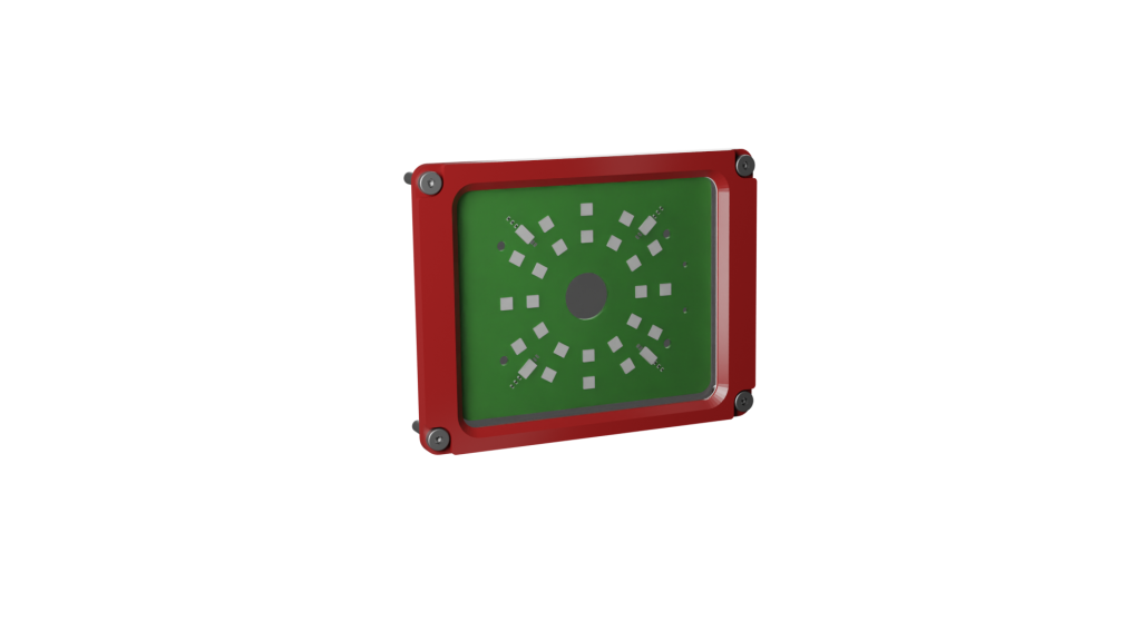
The Loxi1-X light module belongs to the class of direct, internal lighting.
The structure of the light module consists of eight segments with three LEDs each. The light module thus has a total of 24 LEDs, which can be equipped with different wavelengths via the colour coding. Organic surfaces in particular are best imaged with the Loxi1-X module.
//distance measurement
In addition to the LEDs, the Loxi1-X module has 4 TOF sensors with a range of 0 – 65535 and can thus precisely measure the distance of target objects up to 1m away.
The implementation will follow in later software versions.
2. Main Features
- Direct light module
- Individual setting for each LED
- Up to 8 brightness levels for each individual LED
- Distance sensor for distance measurement up to 1m
3. Areas of Application
- Organic surfaces
- Barcodes
- Labels
- Field of view areas
4. color coding
- -R Red (612 – 630nm)
- -G | True Green (513 – 545nm)
- -B | Blue (450 – 480nm)
- -A | Amber (609-624nm)
- -W| White (4000K)
5. Exchange
The light module may only be replaced by a trained specialist and only when it is switched off.
- Shut down the system via the web interface.
- Switch off the power supply of the evoVIU.
- Open the four screws on the front of the evoVIU housing.
- Open the four screws of the Loxi1-X light module.
- Remove the circuit board and place the replacement circuit board in the camera.
- First screw the two screws on the front docker side and make sure that the module is lying straight on the holding surface and the contacts before doing so.
- Now tighten the two remaining screws of the module.
- Screw the front panel back onto the camera.
- Turn on the power supply to the camera.
- If the LEDs flash within the next 30 seconds, you can use the new module.
If you see a light sequence twice within the next 30 seconds, the Loxi module has been detected by the system.
If you do not see a light sequence, then check the setup again. In a few cases, a spring contact may not contact the board properly. If you still have problems, please contact our support.
6. Variant Number
XXXXX-XXX-L1-R | L1-R: Red / L1-G: Green / L1-B: Blue / L1-A: Amber / L1-W: White
