evoVIU Dokumentation
-
Hardware
-
-
- Articles coming soon
-
-
-
Software
-
- Articles coming soon
-
- Articles coming soon
-
- Articles coming soon
-
- Articles coming soon
-
- Articles coming soon
-
- Articles coming soon
-
-
Introduction
-
General & Safety
The custom routines are a relic from earlier versions of the camera. They have now been almost completely replaced by workflows. However, as some of them are still in use, the instructions remain here. However, please be aware that some components now look different or have a different name.
The Weld Seam Inspection Custom Routine is to perform a weld inspection. In the process, it is found out whether the weld seam is qualitatively in order. In this chapter you will learn everything you need to know to perform this custom routine.
1. overview
The purpose of the test is to detect weld defects in internal and peripheral areas. If you don’t know how to create a Custom Routine, check here. You must select Weld Seam Inspection as the routine type.
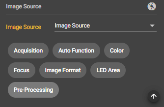
To check your image taken in the Image Source, you can select it in the Custom Routine Configuration Bar under Image Source.
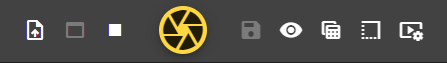
You can upload a reference image using the Upload button on the left side of the Control Bar. This is needed to perform the training. It is important to note that the reference image has the same resolution as the image captured in the image source. With the button next to the upload button you can display the teaching mode, then your reference image appears.
The settings in the Configuration Bar help you to check your weld.
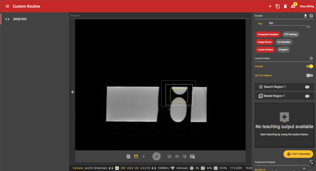
1. Locate Contour
Under the menu item Locate Contour you set which regions of your reference image should serve as reference
Activate
Results are only read if the routine is activated.
Use two regions
If you activate this setting, you can mark two regions on the image and save these seams as a reference.
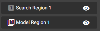
Here you first set which seam of the reference image is to be checked. There are two areas for this. The search region – the initially larger, gray box – includes the area where the suture is searched for. The other white box shows the Model Region, the region that contains the model to be searched. Accordingly, the white box must always be inside the gray box. By clicking on the eye symbol you can show and hide these two boxes. The yellow box only becomes interesting at the next section.
Click on this button to start the teaching. In doing so, they create the reference for how the weld seam should look. Before you start teaching, you should make sure that you have positioned all areas optimally.
2. component analysis
The Component Analysis Region is located in the inner part of the model. Bright regions are detected here.
Number of Test Regions
Here you can set the number of points at which the examination of your image should take place within the model. You can select up to 8 points at which the weld seam is to be checked. To do this, drag the yellow box over the desired location.
For each region, you can make further settings to adjust the tolerances of the respective region.
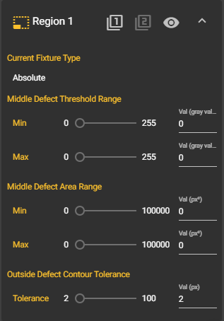
Current Fixture Type
Your Fixture Type is displayed here. You can select either absolute as Fixture Type or a Model Region. You make this selection by clicking on the icons with the 1 or 2.
Middle Defect Threshold Range
Allows you to set the range of gray levels that are allowed in the center region of the model.
Middle Defect Area
Range
Here you can set the range of the permissible error in the middle range of the model. Under Min you enter the minimum and under Max the maximum size of the error.
Outside Defect Contour Tolerance
Here you specify the margin error tolerance in pixels. Here you can set the number of pixels that are allowed when deriving the model contour.
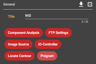
3. FTP
Under the menu item FTP you can specify where you would like to save your images.
FTP Connection
Here you must first create an FTP connection and then select it. You can find more information about this in the Connection section.
Directory
Here you can enter where you want to save your images and what the folder should be called.
Use FTP Transfer
Here you can select whether you want to save the images on an FTP server or not.
4th Program
Under the menu item Program you start the inspection of welds.
By clicking the Play button in the Control Bar, a dialog box will appear where you can enter an order number and an order description. This way you can grant a unique assignment.
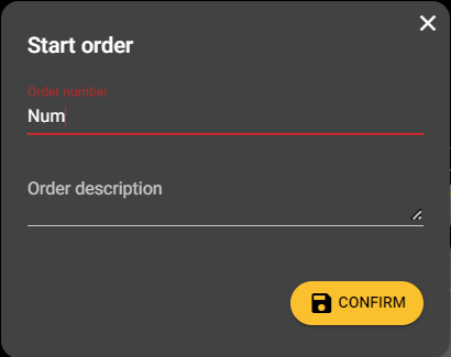
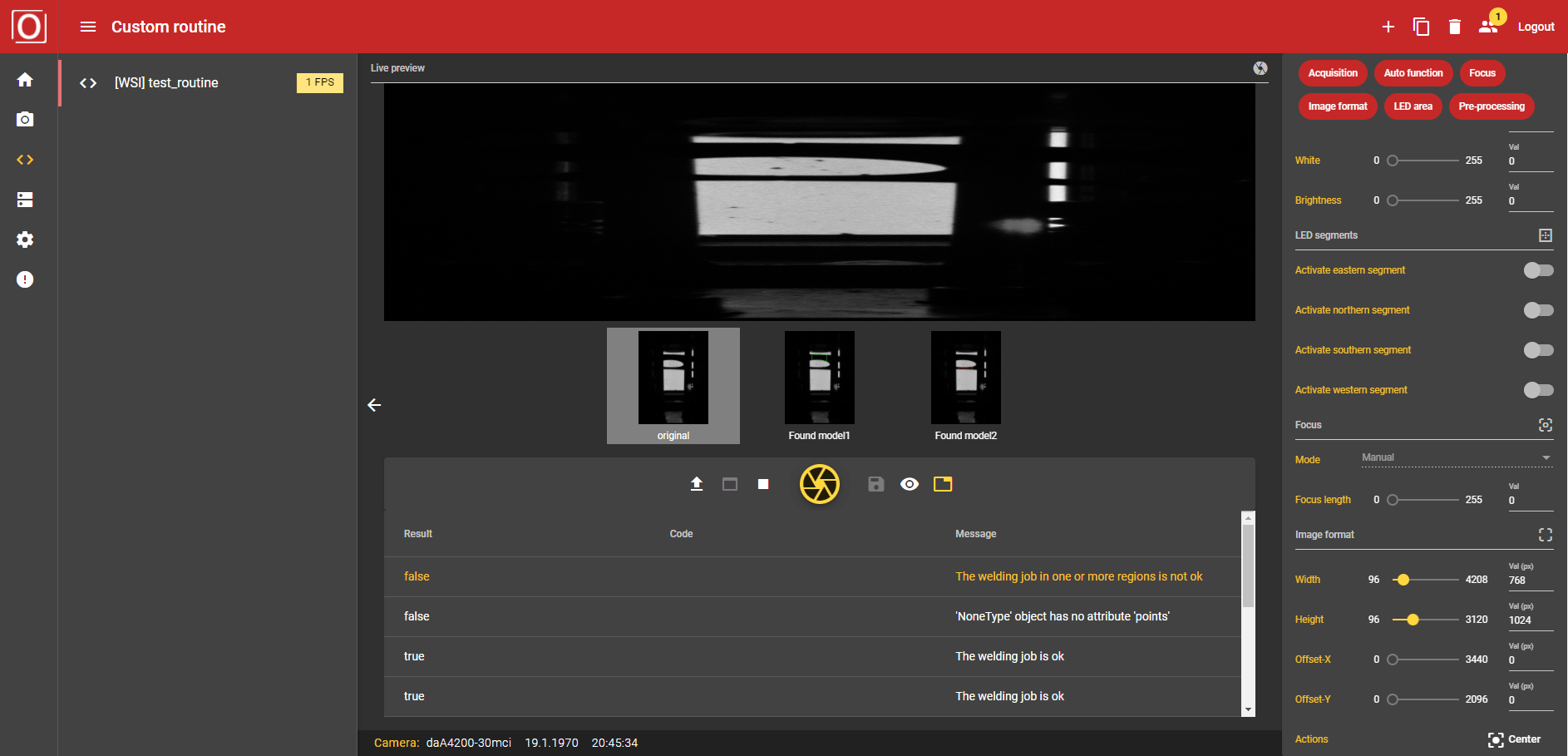
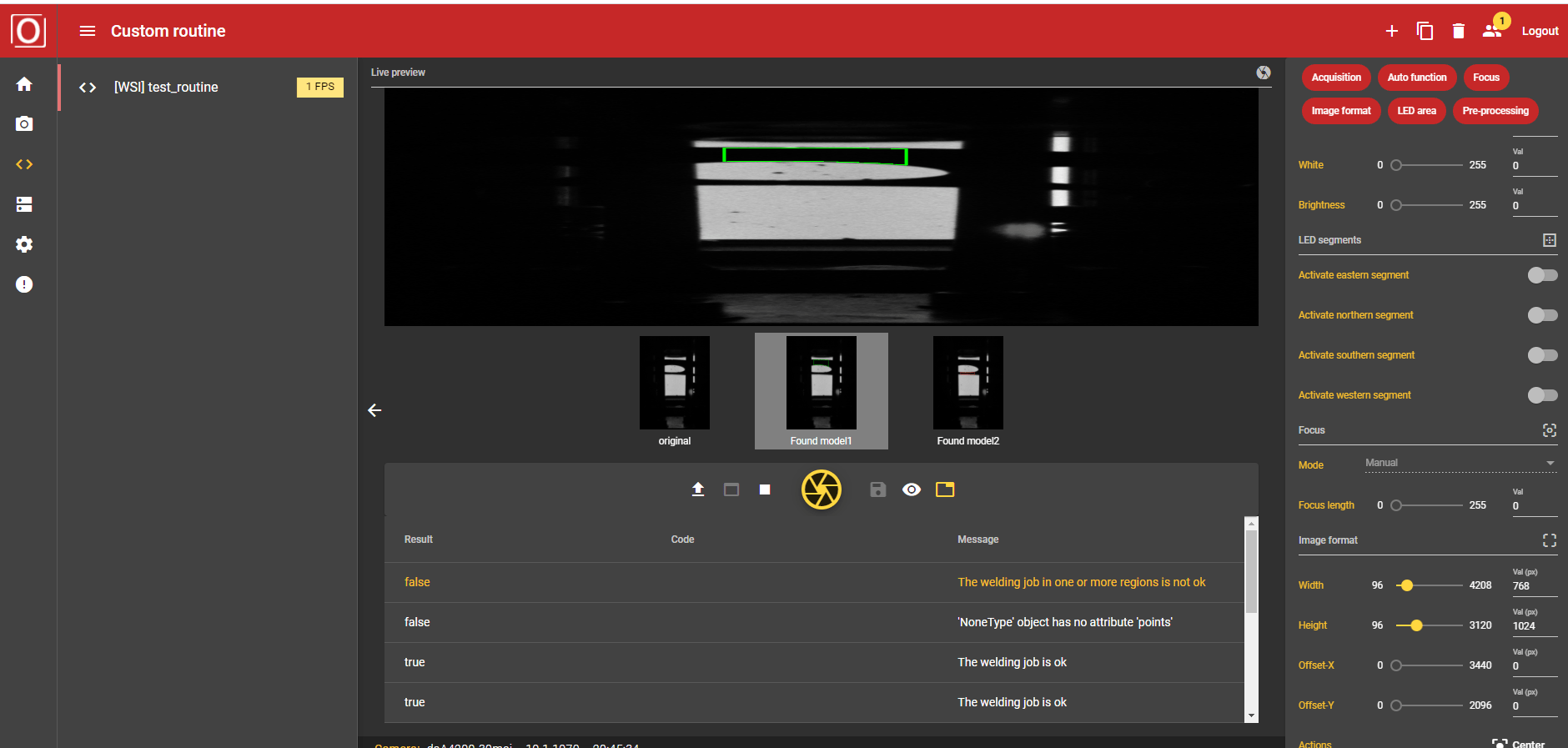
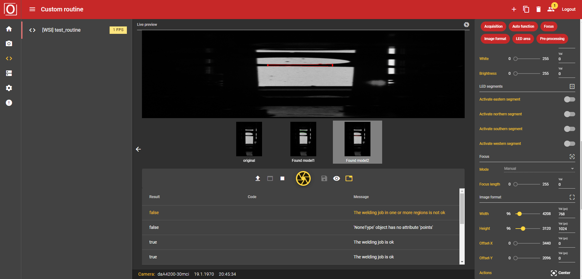
As soon as you have now clicked on Confirm, an image is captured – depending on the capture mode. This is then checked at the marked points to see if the weld is identical to the one you saved during teaching. The result table shows you whether the seams of the captured image are OK or not. If you have specified several regions under Component Analysis, you can see which of the regions are in order. The places are marked green if you are ok and red if not.
5. IO controller
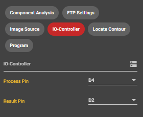
The two pins of the docker of the smart camera can be used to communicate with the outside of the system.
Process Pin
Here you can select whether and if so which pin should be assigned as Process Pin.
Result Pin
Here you can choose if and if yes which pin should be assigned as Result Pin.