The custom routines are a relic from earlier versions of the camera. They have now been almost completely replaced by workflows. However, as some of them are still in use, the instructions remain here. However, please be aware that some components now look different or have a different name.
The goal of the OCR Custom Routine is to be able to read codes, labels or other characters. This chapter tells you everything you need to know to perform this custom routine.
1. overview
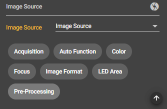
Once you have captured an image in the Image Source, you can select it in the Custom Routine Configuration Bar under Image Source. Without this selection, the routine cannot be started.
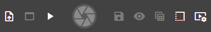
Click on the Play button in the Control Bar to start the stream. Depending on which capture mode you have set, your image will appear as a stream.
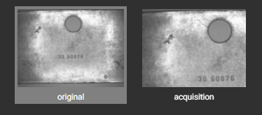
2. acquisition
Switch from the original image to the acquisition image so that you can see your settings directly.
Camera Orientation
This setting allows you to rotate the image. For example, if your code is upside down, you can set the camera orientation to 180.
Acquisition Strategy
Here you can choose between Single Image and Image Fusion.
With Single Image, exactly one image is captured.
Image Fusion uses external light. The component is exposed and photographed from each of the four sides in turn. Once all four images have been taken, they are merged into one. Thus, digits can be recognized better due to the shading.
2. process
Under Process you set the Machine Visionyou need to read out digits or characters.
Process Settings
Training Set
Upload your training set here. The training set contains only digits and the raw image should be processed so that only digits can be recognized.
Use Special Digit Differentiation
If you activate this feature, numbers and letters that are often confused with other numbers or letters because of their similar structure – for example, the 8 and the 0 – are checked again afterwards to see which of the two numbers it is in the end.
Closing kernel
Here you can select a value between 1 and 15. The larger you choose this value, the sooner the gaps between the letters will be closed. This is how small holes in objects are closed by connecting them together.
Largest Noise Area
Here you can select a value between 0 and 10000. With this value you define the size of the disturbance. It is the number of pixels in the area. You can use it to adjust how much noise is allowed in the image.
Note
With Correction Term and Window Size you can make settings for adaptive thresholding. The goal is to determine the appropriate threshold value so that all pixels with a lower value are displayed as white, for example, and all pixels above that value are displayed as black. This way your code or label is separated from the background and can be read.
Correction Term
Use this parameter to make adjustments to the threshold value. The identified mean value is changed by your value set here.
Window Size
Here you set the size of the area in which a local threshold is determined. The larger the value, the larger the area in which the mean value for the threshold is calculated.
Smoothing Kernel Size
Here you set the surface size to be used for smoothing.
Use AI
Enable the button if you want the set to learn with the help of artificial intelligence.
Largest Noise Region
Width
The value you select determines the maximum width of the region in which the Noise Area may extend.
Height
The value you select determines the maximum height of the region where the Noise Area is allowed to extend.
Code info
Width Range Max
The set value determines the maximum width that the letter or digit to be read out can have.
Width Range Min
The set value determines the minimum width that the letter or digit to be read out can have.
Height Range Max
The set value determines the maximum height that the letter or digit to be read out can have.
Height Range Min
The set value determines the minimum height that the letter or digit to be read out can have.
Number of Characters
With this value you can specify how many letters/characters should be recognized or how many letters the code has.
Intensity Level
Here you can choose between dark and light. You can decide whether you want the code/characters light and the background dark or the code dark and the background light.
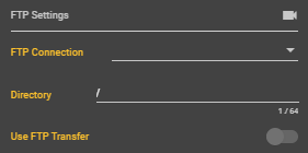
3. FTP Settings
If you want to save your images on the FTP server, you must enter your details here under the FTP Settings.
FTP Connection
Select your created FTP Connection under this item. You can create them under the Connections item.
Directory
Enter the path of your storage location where you want to save your images. Thus, a new folder is created for the operation.
Use FTP Transfer
Here you can select whether you want to use the transfer to the FTP server or not. Only if the button is enabled, images will be saved on your server.
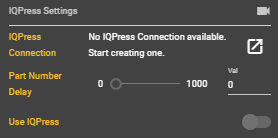
4. IQPress
IQPress Connection
Under this point you can create a new IQPress Connection. IQPress is a database system to which you can assign and extract data.
Part Number Delay
Here you can set an individual delay until a part is called up in the database.
Use IQPress
Here you can select whether you want to use IQPress or not.
5. PLC
Under the menu item PLC you can create a PLC-Connection and thus call a connection via a web interface
PLC Connection
Here you can either select a PLC connection or create a new one. If you click the icon next to this item, a dialog box for creating a new connection will open.
Use PLC
Select here whether you want to use PLC or not.
Data Block
Specify here which data block you want to select.
Start byte
Specify here which byte should be your start byte.
Übersicht
WEBINAR
Optimize processes:
Transformation through modern image processing