evoVIU Dokumentation
-
Hardware
-
-
- Articles coming soon
-
-
-
Software
-
- Articles coming soon
-
- Articles coming soon
-
- Articles coming soon
-
- Articles coming soon
-
- Articles coming soon
-
- Articles coming soon
-
-
Introduction
-
General & Safety
In this chapter, you will learn how to set up a simple workflow. The example should make it clear which steps are required. The aim of the workflow is to read a Data Matrix code.
1. preparation
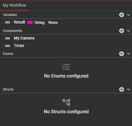
The first step is to create our custom nodes. We can create these in the My Workflow area.
Variables:
We need a variable in which we store the result as a string. To do this, we click on the plus icon under Variables, give the variable a name and select the data type String.
Components:
Timer: We need an initial event so that we can start our workflow. In the My Workflow tab in the Components area, we add a component of the Timer type using the plus icon.
File Camera: We also need a picture for our test. This requires a camera, which we can add in the My Workflow tab in the Components area. For our example case, we select the component of type File Camera. Alternatively, a camera component can also be created if the camera sees Data Matrix codes.
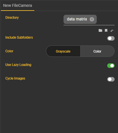
A directory must be specified in the node settings for the file camera. Here we can either access a folder in Files or specify a location where the data is located. We also have the option here of specifying whether we also want to take into account the images in the subfolders, whether the images should be passed on in color or gray values, whether they should only be loaded as soon as they are needed (lazy load) or whether they should always be repeated (cycle images).
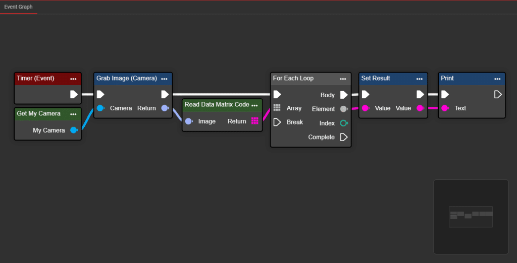
2. assembly
Now that everything is prepared, we can start assembling the workflow in the Event Graph tab. To achieve our goal, we need the following nodes:
-
Timer (Event)
-
Get Camera (Variables)
-
Grab Image (Camera)
-
Read Data Matrix Code (Code Recognition)
-
For Each Loop (Array)
-
Set Result (Variables)
-
Print (Misc)
Nodes can be added either by clicking on the plus icon at the bottom right of the event graph or by right-clicking in the canvas. In both cases, a context menu opens and you can simply search for the required nodes using the search bar.
Once all nodes have been added, they can be connected to each other.
3. implementation
The workflow can now be executed by activating it via the Start button in the Top App Bar.
The results are now visible in the Output window. As we pass the Result variable to the Print node, it is displayed there, for example.
